


Pioneer A-90D Integrated Amplifier - 1987 release
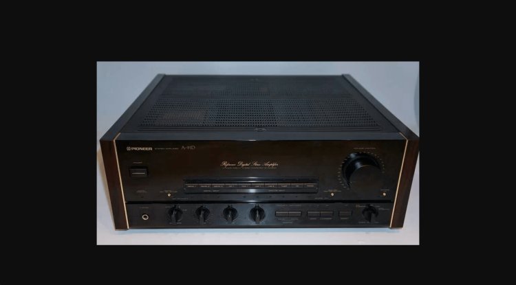
The EX series stereo integrated amplifier eliminates the factor that elaborates an internal design and becomes noise and a distorted cause while incorporating a digital-analog converter.
Two optical inputs and one optical power are carried by the digital input/output.
When an optical fiber bends or vibrates, an optical-transmission distorted corrective network is carried in each side of an input and an output, and the noise is stopped low to prevent the width of a pulse shifting and pulse width distortion from arising.
While losing the phase difference by carrying a digital-analog converter in each L/R in the DAC stage, the separation improves by separating L/R.
In order to use a PLL with a very high Jitter suppression effect as a PLL that generates a clock in order to prevent tone-quality failure due to a Jitter (shake of the edge of a clock) and also to avoid the influence of an oscillation, the oscillator circuit is bonded using a special resin.
The clock is used as one master clock during a digital-analog-converter operation, losing the asynchronous clocks (microcomputer clock, etc.) that are currently oscillating, and suppressing the presence of the unneeded beat component.
By oversampling four times, the digital filter turned the superfluous high region component into the high band and eliminated the Loopback noise.
A very efficient IC is used as a digital filter, achieving less than 0.0001dB and 100dB inband ripple attenuation.
The 5th Bata Wace type low pass filter, which was the outstanding in-phase response, is composed of an FDNR discrete circuit, and phase distortion is reduced by considering it as a more gently-sloping feature.
Full high-quality sound-ization is achieved, such as a high-quality sound part and grounding using the oxygen-free-high-conductivity-copper version busbar.
The digital recording selector is carried, which can record to DAT the digital source that is different from the sound that is now being taken out of the speaker with a digital signal. (This functionality is only available while viewing and listening to analog sources.)
Another substrate separates analog portions, such as digital circuits such as data demodulation, PLL, and a digital filter, a digital-analog converter, and an analog low pass filter, and the digital part is insulated.
The analog system is protected from stonewalling, which causes a tone-quality failure by isolating power sources, such as a digital circuit and a microcomputer, and the power supply of an analog system from a transformer.
The direct construction method is used to achieve signal path shortest-izing and optimal placement-ization.
First, the digital and analog parts were separated, and the signal path after becoming an analog signal was shortened in the same way as other analog sources. By separating each input block and shielding an I/O block, failure and signal interference within are avoided.
Furthermore, in the input block, the input & recording selector was made into a structure that may run the main volume physically and electrically by remote control, and the shortest-ization of a signal path was achieved.
When a source direct switch point is enabled, all input sources other than Adapt/Tape2 termination are routed directly to the main volume, resulting in a cleaner sound.
Along with the fluency of a signal, a power amplifier block is arranged, and the output of the power stage is routed directly to a speaker selector.
The product-line distance from a power-source part is also engineered to be as short as possible.
Because priority is given to Termination A while achieving direct installment and shortest-ization for a termination to the substrate attached to the relay, A termination is situated downward in the speaker selector block, contrary to the normal termination location.
To put into practice and suppress an oscillation, an original honeycomb form with frame chassis is used.
It is in a bottom plate and a bonnet case about the honeycomb according to a stop in order to avoid a power transformer oscillation and vibration from punching to a transformer frame and a frame chassis.
In order to sustain a large transformer, a cast-iron insulator with five flat knots is used.
Cast iron was used as the transformer case, and the radiation fin was prepared while being filled with the thermally conductive good pitch material between the cast-iron case and the main unit of a transformer. This prevents the internal resistance of the transformer coil from increasing due to temperature rise.
It was difficult to create electromagnetic induction, and the bulk newly designed seal dead capacitor, which is difficult to obtain, was used.
And in the volume, the method of maintaining the weight balance of both ways focusing on the bearing of a rotary knob is used. In order to prevent mechanical stress from starting a volume main unit entirely and to keep the influence of an amplifier oscillation to a minimum.
Switching distortion has adopted the non-switching circuit TypeIII, which is theoretically not formed.
While stabilizing the idle current that is carrying out the drift and suppressing the occurrence of thermal distortion caused by changes in outside temperature, etc., immediately after power-switch ON and at the time of the Taishin number input, the voltage amplification stage and the power amplification stage are clearly separated, and the speaker drive capacity at low load intensity is increased.
The newly created seal dead capacitor, which connects the aluminum casing to the cathode of the aluminum electrolytic capacitor, is more likely to be used, and the capacitor element is powerfully shielded.
Running out of the noise from diving and the capacitor itself of noise was lost as a result of this, and a high S/N was realized.
When not listening to a record, the circuitry turns off automatically, and the Phono equalization section minimizes unwanted noise and adds to the improvement of the tone quality of other sources.
The recording selector has ON/OFF capability; it runs only while the TONE direct switchpoint ON is utilized, and a clock stops after that.
As the circuitry of a Phono equalization, the high Brit MC transformer method is used.
Copper plating is used as a rear panel, a bottom plate, a transformer frame, and a speaker terminal block shielding case to reduce distorted banishment of an electromagnetic and an oscillation.
The very-thick OFC polarity attached-indicator power cord is used.
Furthermore, it is a fuse for audio, and aluminum Naked shaving and quality parts are thrown in, such as a large-sized terminal a thing rotary knob, a gilded input/output terminal, and vice kind.
| Form | An Integrated Amplifier with a built-in digital analog converter |
| <Amplifier part> | |
| Output power (both channel drive, 20Hz - 20kHz) | 180W+180W (4 ohm, 0.005%) 150W+150W (6 ohm, 0.003%) 120W+120W (8 ohm, 0.003%) |
| Dynamic power | 400W+400W (2ohm) 280W+280W (4ohm) 160W+160W (8ohm) |
| THD (20Hz - 20kHz) | 0.003% (8ohms) |
| Input sensitivity/impedance | Phono man month: 2.5mV / 50kohm Phono MC: 0.25mV/40 ohms compact disk, Tuner, Line, Tape:150mV /, 50kohm |
| Maximum permissible input (1kHz, 0.008%) | Phono MM:200mV Phono MC:20mV |
| An Output voltage/impedance | Tape Rec, Rec Out:150mV /, 0.8kohm |
| Frequency characteristic | Phono man month: 20Hz-20kHz 0.2dB Phono MC: 20Hz-20kHz }0.3dB compact disk and Tuner:1Hz-200kHz+0 -3 dB |
| Tone control (Volume-40dB) | Bass: 100Hz, }8dB Treble: 10kHz, }8dB |
| Subsonic Filter | 7Hz, 6dB / oct |
| Loudness contour (Volume-40dB) | 100Hz : 5dB, 10kHz : 3dB |
| S/N ratio (IHF, A network, a short circuit) | Phono man month: 95dB (5mV o'clock) Phono MC: 83dB (0.5mV o'clock) compact disk, Tuner, Line, DAT/Tape1, 2:110dB |
| <Synthesis> | |
| Supply voltage | AC100V, 50Hz/60Hz |
| AC outlet | Power-switch interlock: Two lines (200W) Power-switch un-interlocking.: One line (100W) |
| Power consumption (Electrical Appliance and Material Control Law) | 365W |
| Dimensions | Width 457x height 173x depth of 475mm |
| Weight | 29.3kg |